• For details about Moxtek employment opportunities, please visit the Careers page

  • This field is for validation purposes and should be left unchanged.
Thursday, 27 March, 2014
The Moxtek® Proflux® UVD260 and UVD240 analyzers provide superior broadband performance in spectroscopy applications ranging from 240nm in the Deep UV up to 3.3μm in the mid-wavelength infrared. Moxtek Proflux designs utilize wafer-scale aluminum Nanowire® fabrication technology to produce the finest-pitch commercial wire-grid polarizers on the market. These deeply sub-wavelength optics offer the benefits of conserved space, an exceptionally wide field acceptance angle, minimal performance variation with wavelength, and none of the dramatic short-wavelength infrared disturbances present in Glan-Taylor and Glan-Thompson polarizers.
Picture1

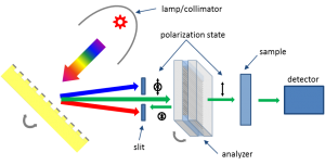
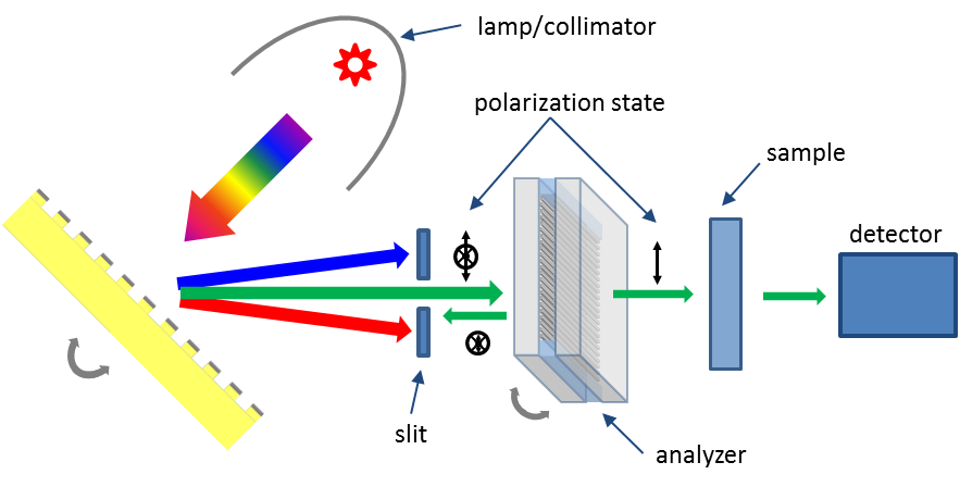
Figure 1: Simplified spectrophotometer with analyzer.

Performance Improvement

Figure 1, depicts the light path for a simplified spectrophotometer with polarizing analyzer. This type of arrangement is useful when examining dichroic and birefringent samples, diffraction gratings, or when characterizing samples in reflectance. Typical polarizers used in this analyzer application are based on the Glan-Taylor (GT) or Glan-Thompson (GTh) designs, which generally utilize Calcite prisms. Unfortunately, inherent absorption in calcite and scattering from inclusions and impurities can severely limit UV transmittance and achievable signal to noise ratio in GT and GTh designs. The ProFlux UVD Series polarizers by Moxtek offer an alternative with dramatically improved deep UV transparency for better signal to noise ratio performance. 
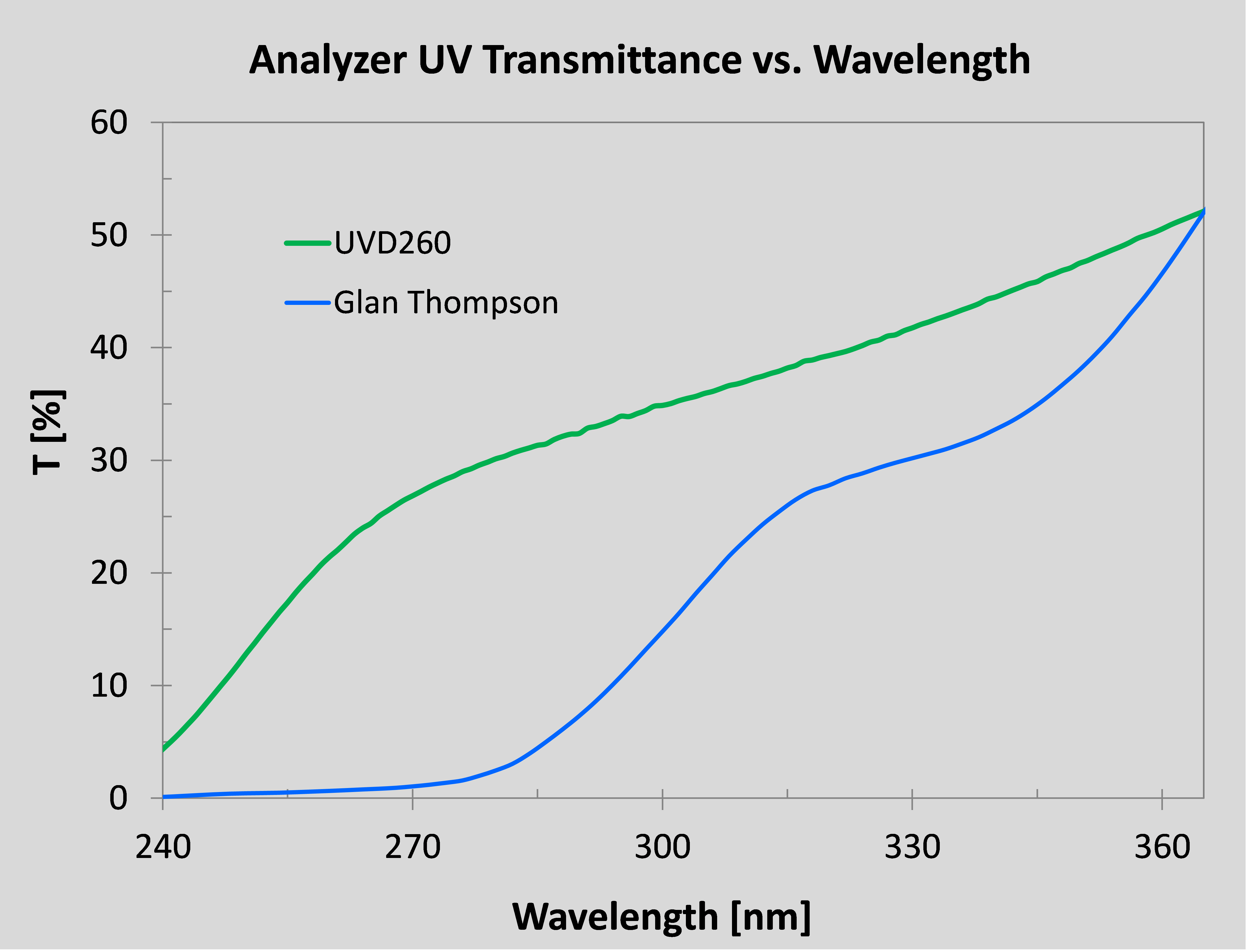
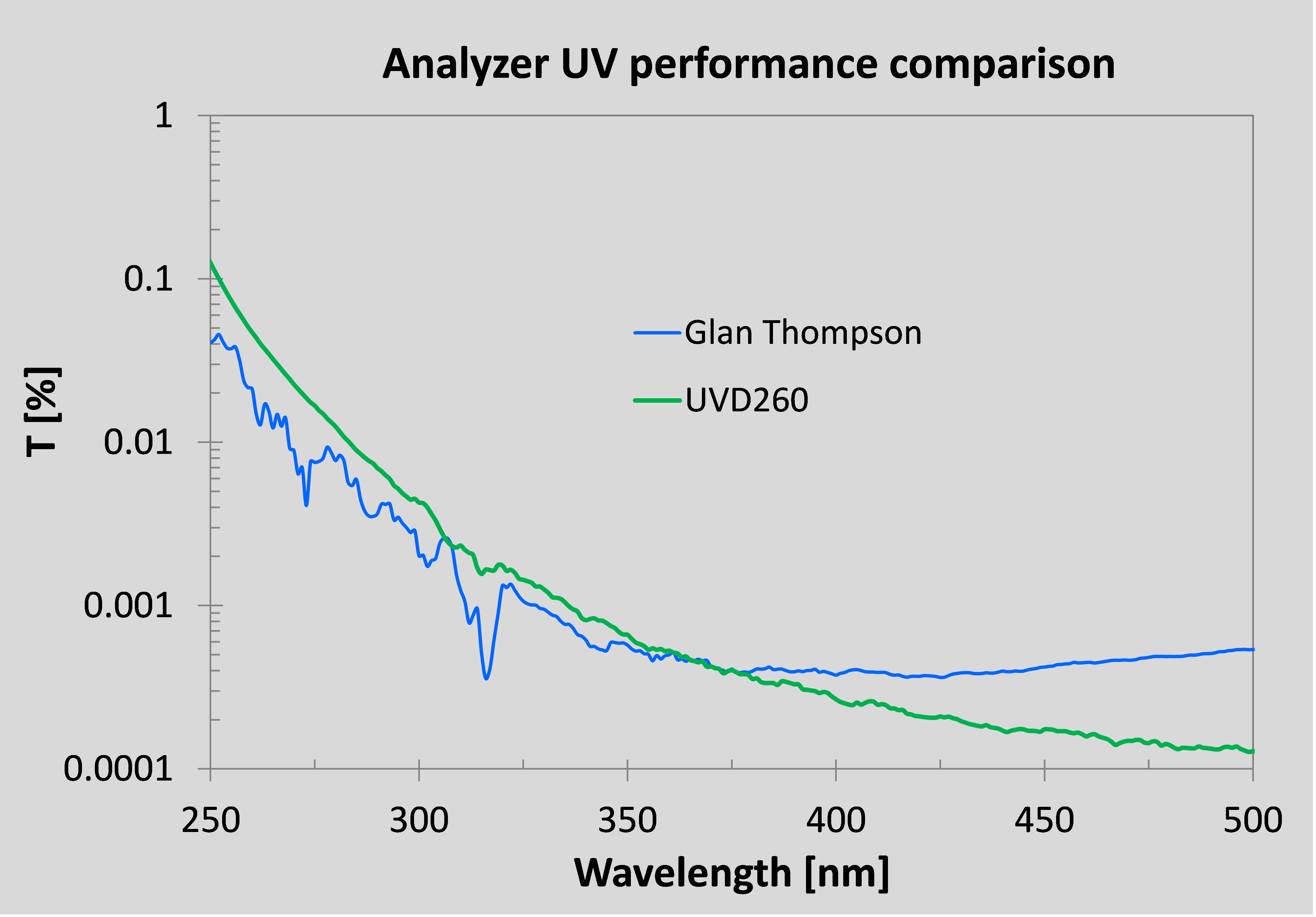
Figure 2a compares the UV passing state transmittance for a standard calcite GTh analyzer and the Moxtek UVD260, while figure 2b compares their performance when measuring the blocking state transmittance of a reference polarizer. The GTh analyzer shows a dramatic reduction in UV light throughput resulting in a poor signal to noise ratio, while the UVD260 is fabricated on fused silica and maintains excellent performance well into the deep UV.
figure 2c

Figure 2a: Performance comparison of ProFlux UVD260 and Glan-Thompson polarizers in an analyzer application. Analyzer passing state UV
transmittance comparison.

figure 2d

Figure 2b: Performance comparison of ProFlux UVD260 and Glan-Thompson polarizers in an analyzer application. Reference part measurement.

Infrared Performance

The Glan-Taylor (GT) and Glan-Thompson (GTh) polarizer designs consist of two birefringent prisms mounted with their diagonal faces either separated with a small air gap (GT), or filled with an optical cement (GTh). The separation of an incoming beam into orthogonal polarization states relies on total internal reflection and thus imparts strict requirements on beam collimation and entrance angle. Since refractive index generally decreases in the infrared, this results in a decrease in the allowed deviation from normal incidence for the GT and GTh polarizer designs. For spectroscopic applications, where beam collimation is usually far from ideal, this results in significant leakage of the unwanted polarization state. While the GT and GTh polarizer designs can typically only tolerate a few degrees of entrance angle misalignment or a narrow field (cone) angle before performance deteriorates, wire-grid polarizer performance is relatively angle and wavelength insensitive and shows practically no IR leakage of the unwanted polarization state. The ProFlux UVD designs can easily accommodate ±20 degree variations from normal incidence with minimal performance variation. This corresponds to a field angle of 40 degrees, which allows for dramatically improved light utilization when using poorly collimated sources and eases any alignment concerns. 
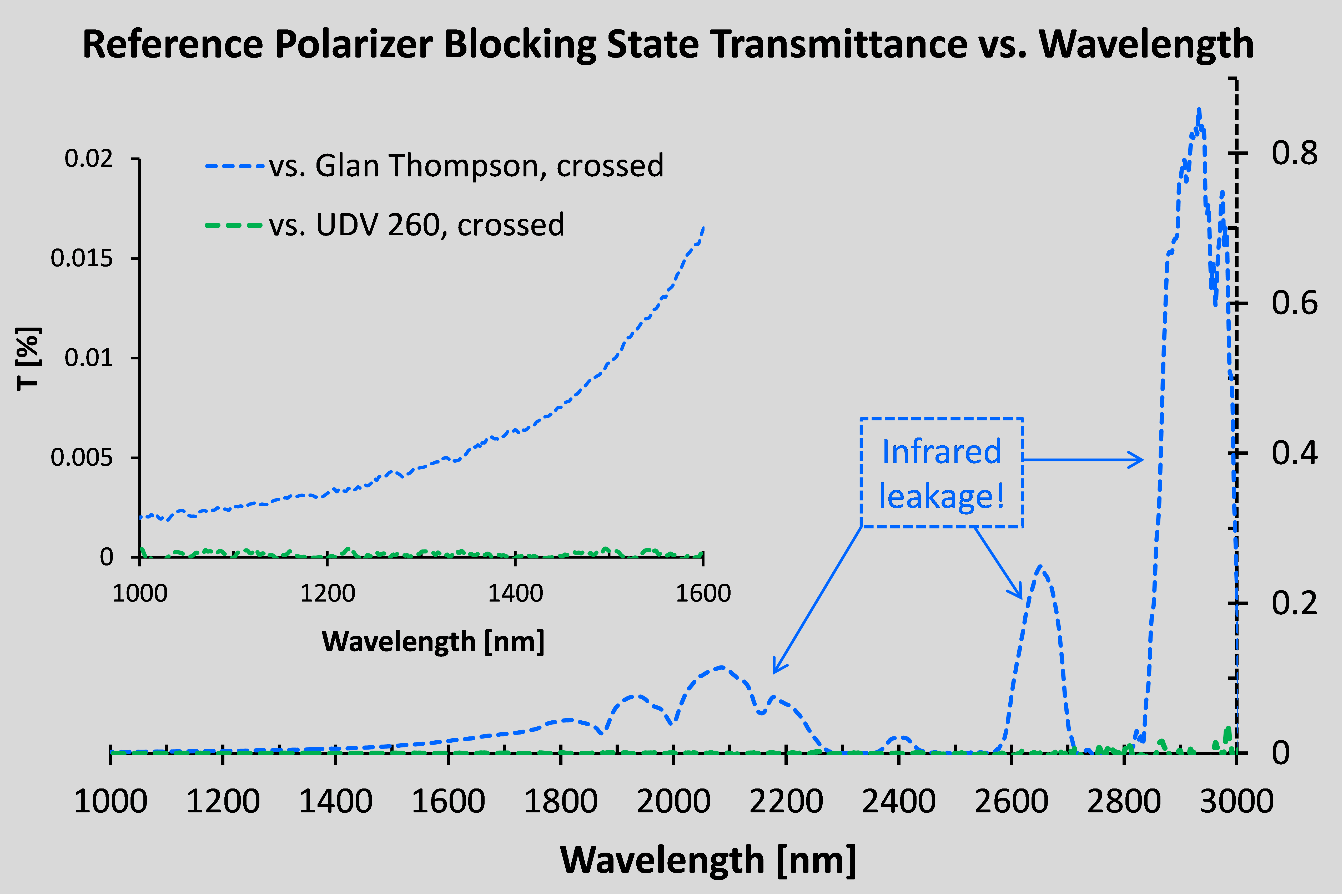
Figure 3a depicts the dramatic difference in infrared performance between a GTh polarizer and the ProFlux UVD260 when analyzing the same part (another UVD260). In addition to the increased leakage at longer wavelengths due to the limited field of view of the GTh design (see inset), there are strong peaks, likely due to IR absorption resonances from calcite and impurities (e.g. moisture). The Kramer-Kronig relationship dictates that any absorption resonance is also accompanied by an incongruity in the index of refraction, which should manifest itself in the field acceptance angle. By comparison, the UVD260 analyzer shows no such infrared leakage or resonance peaks due to its sub-wavelength grating design and fused silica substrate. The transmittance of the GTh and UVD260 polarizers in the passing state are depicted in Figure 3b. The same absorption features responsible for the IR leakage peaks in the GTh blocking state measurement are also apparent here in the passing state. The moisture absorption line at ~2725 nm is much stronger in the hygroscopic calcite material of the GTh than in the UVD260, which is composed of aluminum and infrared grade fused silica. For enhanced short-wavelength infrared throughput and signal to noise, the UVD260 is clearly superior.
figure 2a

Figure 3a: Infrared performance comparison of UVD260 and calcite Glan-Thompson analyzers. Blocking state transmittance measurements of the same reference polarizer using GTh (—-) and UVD260 (—-) analyzers. Inset shows magnified scale away from absorption resonances.

figure 2b

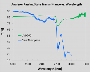
Figure 3b: Infrared performance comparison of UVD260 and calcite Glan-Thompson analyzers. Blocking state transmittance measurements of the same reference polarizer using GTh (—-) and UVD260 (—-) analyzers. Inset shows magnified scale away from absorption resonances.

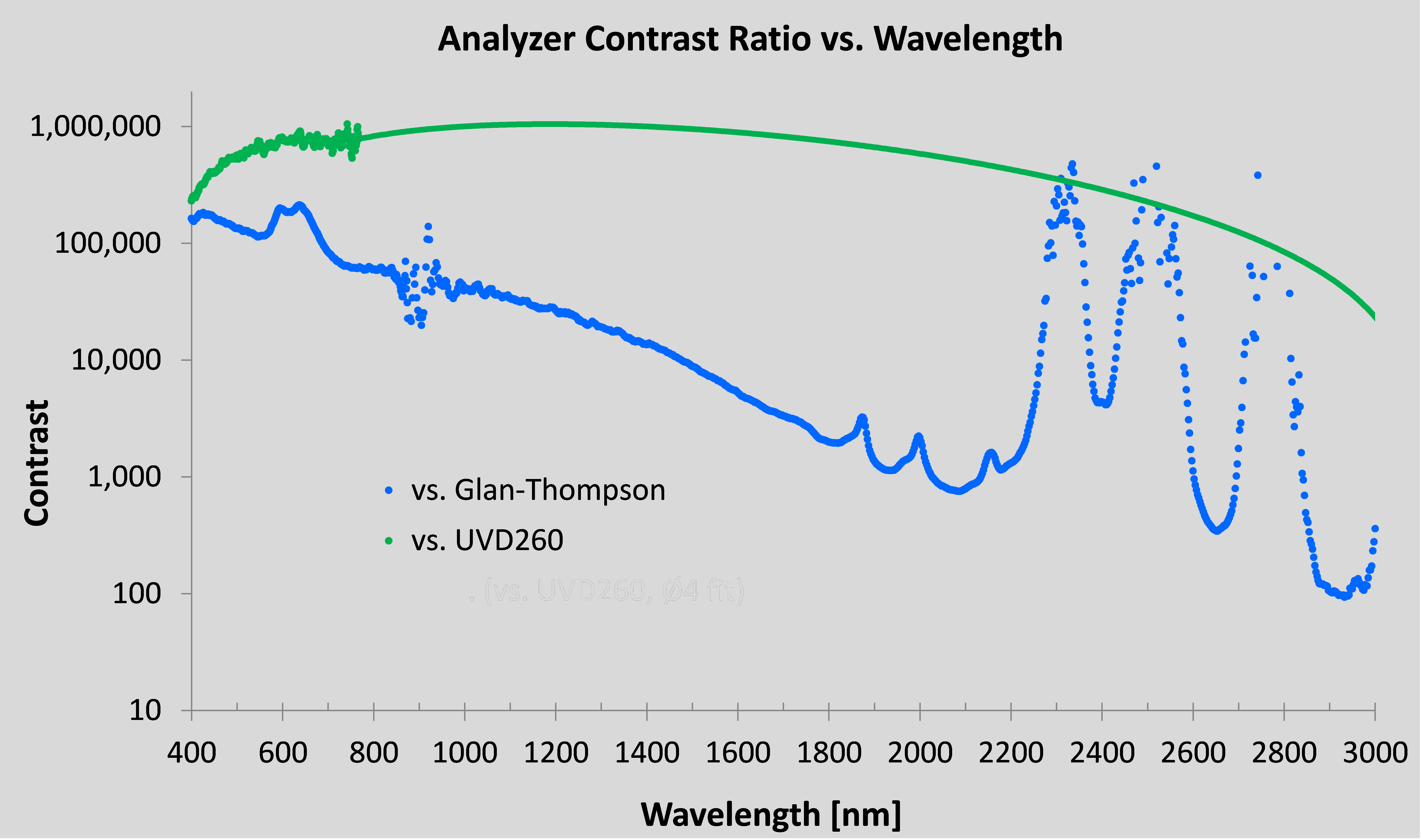
Figure 4 depicts the contrast ratio between passing and blocking state transmittances (inverse of extinction ratio) for UVD260 and GTh polarizers. The GTh infrared leakage has a dramatic effect on the contrast, thus the wire-grid design is preferred for demanding IR spectroscopic applications.
figure 4

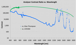
Figure 4: Contrast ratio between passing and blocking state transmittances for ProFlux UVD260 (—) and Glan-Thompson (—) polarizers.

Environmental and Form Factor Considerations

The UVD260 utilizes similar materials to Moxtek’s standard visible spectrum wire-grid polarizer products, which are recognized for their excellent sustained performance in high temperature and high humidity projection display applications. Furthermore, the buried nanowire design of the UVD series helps protect against handling damage and environmental contamination. Whereas the infrared performance of calcite GT and GTh polarizers can noticeably degrade with time due to moisture uptake, the UVD Series wire-grid polarizers are fabricated on non-hygroscopic fused silica and do not show significant performance degradation in humid environments. Due to the total internal reflection operating principal and large critical angle, GT and GTh polarizers have large aspect ratios between their length and clear aperture dimension. As aperture size increases, this aspect ratio requirement ensures the prism-based designs take up much more space in an optical system than the planar wire-grid polarizer configuration, which has a fixed thickness (usually 2.1 mm) set by the substrate choice and spacer thickness. For the UVD series wire-grid polarizers, the physical space required along the beam propagation direction remains fixed, regardless of the choice of aperture size. As a side effect, for larger aperture size GT and GTh designs, the length of the prisms also increases, which degrades performance in the UV and short-wave IR regions due to absorption and scattering. ProFlux UVD Series polarizers are capable of covering the entire spectral range of most spectrometers from deep UV through shortwave IR using the same part and without having to discard light from the larger field angles required when utilizing finite-sized broadband light sources. For GT and GTh polarizer designs, in order to dump the internally reflected beam, the prism sides have either an absorptive coating or are highly polished and housed in an absorptive case. However Fresnel reflections can still occur, leading to leakage of the unwanted polarization state through the exit face of the polarizer. ProFlux UVD Series polarizers separate the beams at the wire-grid surface by an anisotropic absorption and reflection mechanism, and do not rely on birefringence and total internal reflection. This eliminates the long optical path length and absorptive surface/casing requirements inherent in GT and GTh products as well as the unwanted IR performance variation with wavelength. Table 1 summarizes the design, form factor and environmental differences between wire-grid and Glan-prism based designs.
FeatureProFlux UVD260ProFlux UVD240Glan-Taylor / Glan-Thompson
Angle of Incidence, AOI±20°±20°±4 / ±6°
Length2.1mm (aperture independent)2.1mm (aperture independent)Scales with aperture size
IR DisturbancenonenoneDispersion & absorption induced
Fresnel DisturbancenonenoneNeed absorptive coating / case
Spectral Range260-3300nm240-3300nmBroadband performance often requires two sets of polarizers
Table 1

Conclusion

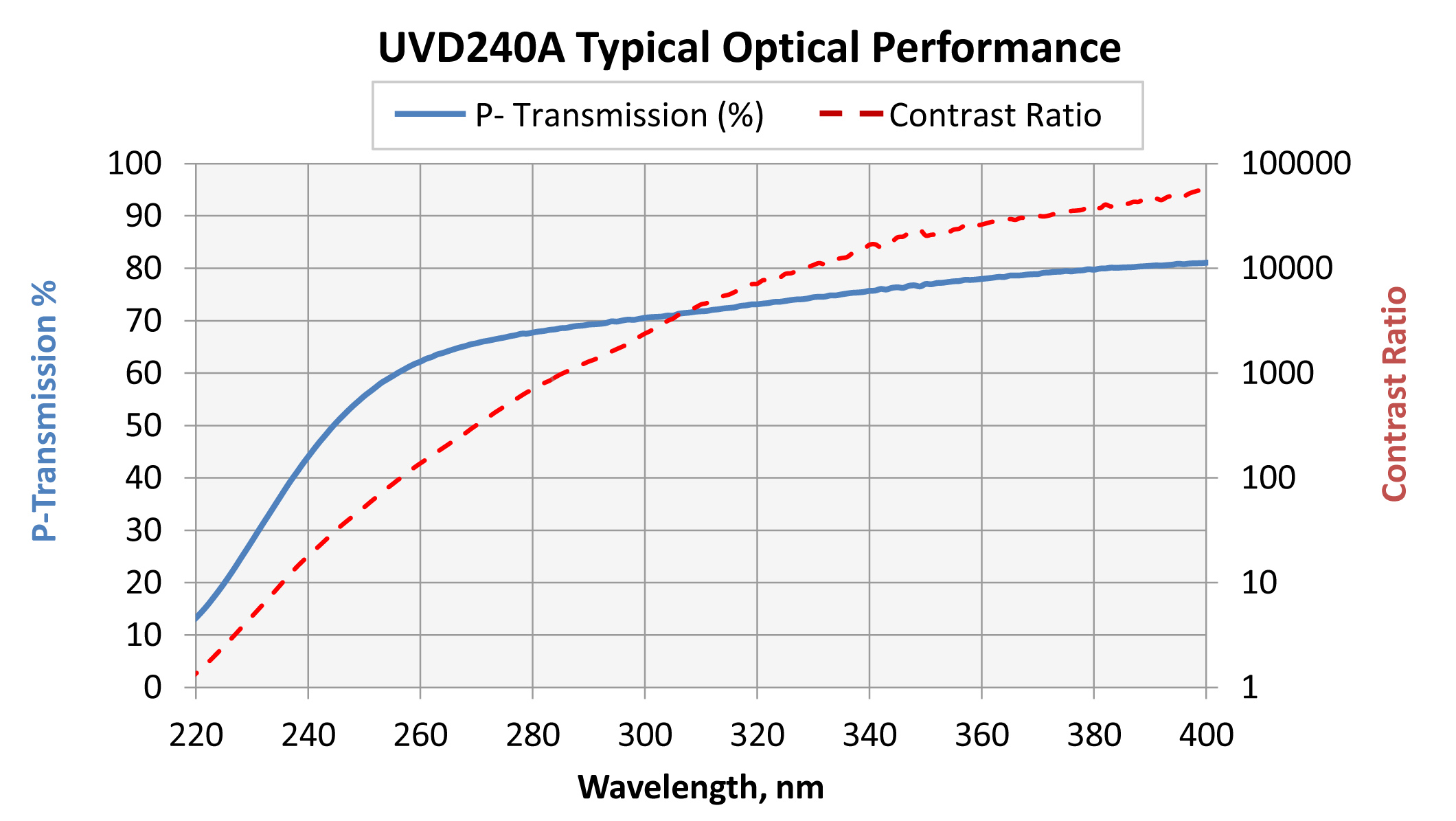
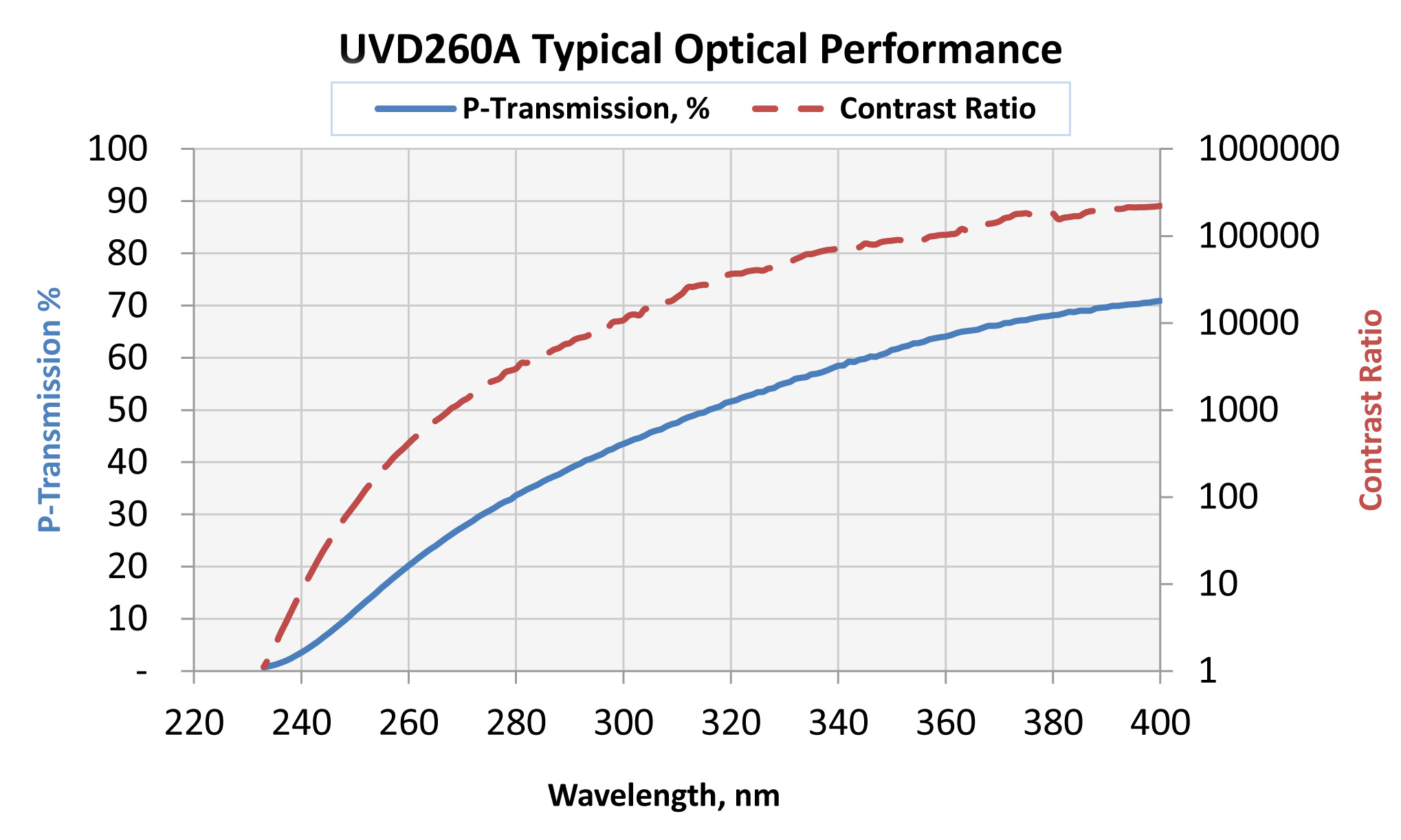
When compared to Glan-Taylor and Glan-Thompson designs, the ProFlux UVD Series polarizers provide superior broadband performance for polarization sensitive spectroscopic applications. The aluminum Nanowire grid design on fused silica substrate is deeply sub-wavelength, providing excellent contrast and outstanding passing state transmission with minimal performance variation from the UV to the short-wave IR. The wide acceptance angle and space-saving form factor improve performance and efficiency while easing system design. See Figure 5 below for typical broadband performance plots.
uvd240

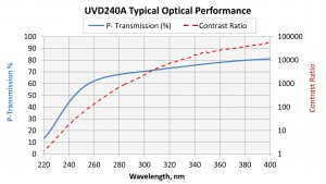
Figure 5a: Typical ProFlux UVD 240 series broadband performance plots for passing state transmittance (Tp) and contrast ratio (passing state / blocking state transmittance).

uvd260

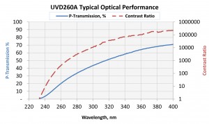
Figure 5b: Typical ProFlux UVD 260 series broadband performance plots for passing state transmittance (Tp) and contrast ratio (passing state / blocking state transmittance).

Category: Comments (0)
Thursday, 27 March, 2014
The Moxtek® wire-grid polarizer technology offers a reliable, highly durable solution to high quality LCoS display technology with a perfect polarization match to the LC imager. Recent improvements in the polarizing beam splitter (PBS) technology enable a 10% improvement in efficiency.
PBS Improvements graph

Figure 1: Beamsplitter Efficiency Comparison (Typical)

Introduction

This technical brief compares imaging needs and how Moxtek is improving its products. It explains how competing technologies in LCoS projectors compare in terms of brightness, performance, durability and reliability.

PBS Efficiency

Efficiency (Tp*Rs) for a polarizing beamsplitter is a measure of how perfectly a polarizer converts randomly polarized light into (reflected) s and (transmitted) p polarized light. If all of the light is converted, then the beamsplitter would be 100% efficient. In reality, some of the light is absorbed, some ‘s’ is transmitted and some ‘p’ is reflected, reducing the efficiency. The Moxtek standard PBS is typically 81% efficient at 550nm wavelength. Recently, with improved manufacturing techniques and new wire-grid technology, this efficiency has been dramatically improved. Figure 1 shows the improvement in efficiency for the Moxtek High Efficiency PBS (HEPBS) versus standard PBS. This represents a 10% improvement.
ElementProFlux Wire GridDichroic PolarizerMacNeille Polarizer
Polarizing MechanismPolarizer using a nano-
structured thin film
Resonant absorption in thick stretched filmReflects s-polarization and transmits p-polarization
SignificanceA perfect polarization match to the LC imager, even skew rays can align to the LC. PBS: f/1.5 and below.
PPL: f/1.0 and below.
Thick polarizing film results in beam depolarizationPolarization direction depends on incoming ray: skew rays are not aligned to LC
ContrastExcellent brightness, contrast, and on-screen
uniformity
Reduced contrast and uniformityReduced contrast and uniformity
DurabilityMade from all inorganic
materials for high durability
Polymer film degrades over time and in high flux conditionsRequires polymer waveplate for correct polarization
Table 1 Comparison of Technologies

Comparison of Other Technologies

Table 1, “Comparison of Technologies”, shows a comparison of wire-grid polarizer, stretched polymer absorbing films (dichroic polarizers), and Brewster’s angle polarizers (MacNeille cubes). Flatter response of ProFlux polarizer across both wavelength and angle creates a more uniform picture from the projector. The wide acceptance angle allows for small f/# optical designs while maintaining color and contrast uniformity. Figure 2 shows an angular map comparison of the Proflux Beam Splitter and the MacNielle Cube.
High efficiency figure 2

Figure 2: Angular Map Comparison between a Moxtek Wire-Grid Beamsplitter measured in reflection at 550nm (left), and a MacNeille Cube measured in reflection at 550nm (right).

Figure 2 shows the center of the circle is a 45ᵒ angle of incidence on the plate. The radius of the circle is 33ᵒ, representing behavior over an f/0.9 cone. The ProFlux beam splitter shows no TIR cutoff, and may be used at a much smaller f/# than the MacNielle PBS, retaining high contrast. Figure 3, “AOI Comparison for Proflux Wire-Grid and Dichroic Polarizers”, shows how the flat response of ProFlux for rotation in both axes is an indication of its superior performance with skew ray polarization. Dichroic sheet depolarization reduces the ability to maintain high polarization contrast in optical systems. High efficiency figure 3a
High efficiency figure 3b

Figure 3: AOI Comparison for ProFlux Wire-Grid and Dichroic Polarizers

Conclusion

An important advantage of the ProFlux PBS over a MacNeille cube is the direction of polarization. A cube polarizes in a direction defined by the orientation of the incoming ray, that is, by the plane of incidence. Because the plane of incidence changes as the skew ray direction changes, uniform polarization over a large cone is impossible for a standalone cube PBS. ProFlux PBS, on the other hand, polarizes relative to the direction of the wire-grid structure. Rays along the principal axis, as well as skew rays, are all polarized in the same direction. This has been called a Cartesian polarizer and is a critical quality for good PBS polarization. Using ProFlux PBS polarizers creates improved full screen performance by providing uniform polarization brightness and contrast across the entire angular aperture at the PBS. The ProFlux PBS is now available as HEPBS, providing a 10% improvement in efficiency.
Category: Comments (0)
Thursday, 27 March, 2014
Energy Dispersive Spectroscopy (EDS) instrument manufacturers and research labs are continually pressing for x-ray components that enable higher performance at a lower cost. High performing x-ray detectors are critical to building quality instruments. Moxtek® has improved the sensitivity of our Si-PIN detectors by using thicker diodes and thinner beryllium windows. The increased performance enables faster sample times, improved sensitivity, and expanded range of photon detection.

XPIN-BT-Detector

Detector Diode Thickness

Improved Energy Resolution At short peaking times, where the shot noise has very little impact on the resolution, the two dominant noise sources—thermal and 1/f—depend very strongly on the total capacitance between the anode and any grounded or DC-biased conductors (see Figure 1). Therefore, reducing that capacitance has an enormous impact on the detector resolution.

detector noise components

One way to reduce the capacitance of a PIN diode detector is by making the diode thicker. For example, a 400-μm diode has an anode-to-backside capacitance of 1.6 pF, whereas a comparable 625-μm fully-depleted diode has a capacitance of only 1.0 pF (see Figure 2). Two challenges involved in making Si-PIN diodes thicker: 1. Full depletion requires either a higher voltage bias or silicon material with a higher resistivity. 2. Diodes with thicker depletion regions have larger volumes and therefore higher leakage currents, so using a diode manufacturing process that results in very low leakage currents is essential. Moxtek has developed Si-PIN detectors with 625μm and 875μm diodes (875μm device is currently in research and development stages) which have lower capacitance resulting in better energy resolutions than the 400μm devices, especially at short peaking times which make higher count rates possible. The thicker devices offer performance advantages that begin to approach SDDs but at a much lower price (See Figure 3).

reducing diode capacitanceenergy resolution vs peaking time

Higher Energy Absorption

Another advantage of thicker Si-PIN diodes is greater energy absorption at the higher energies which is important for heavy elemental analysis. Figure 4 shows the absorption curves of three different diodes thickness. Note that at energies above 25 keV, the 625μm device has about 50% greater absorption efficiency than the 400μm device.

diode absorption curvesDB transmission curvesphoton detection curves

New! XPIN™ Detector Platform

The XPIN™ is Moxtek’s next generation Energy Dispersive X-ray Fluorescence detector (EDXRF). The XPIN takes advantage of thicker Si-PIN diode material as well as thin beryllium windows providing optimal energy resolutions and x-ray photon sensitivity. The XPIN comes in multiple configurations for design flexibility for a variety of industrial EDXRF applications.
XPIN-BT-Detector

XPIN-BT

XPIN-XT-Detector

XPIN-XT-AB (Angle bracket sold separately)

Small

XPIN-XT-HS (Heat sink sold separately)

Category: Comments (0)
Tuesday, 25 March, 2014
DuraBeryllium X-ray window

DuraBeryllium Plus X-ray window

DuraBeryllium® Plus windows are Moxtek’s most robust coated beryllium x-ray window. This window has an additional thin coating of polymer “Plus” applied to the already robust DuraBeryllium window. The Plus layer is more resistant to water and other harsh chemicals. DuraBeryllium Plus windows successfully withstand continuous exposure to heated water as well as to other chemicals. A series of tests were completed on DuraBeryllium windows as seen in the test summary below. Part 1 of this application note details exposure of DuraBeryllium Plus to water, KOH, and HCl. Part 2 will be released later in 2012 and will include details of exposure of this window to other harsh chemicals.

X-ray Transmission

DuraBeryllium protective layers provide corrosive shielding as well as a hermetic barrier to the beryllium foil. These protective layers are very thin and the resulting x-ray attenuation is equivalent to about 1μm of beryllium, having little impact on x-ray transmission. See chart below. corrosion resistance part1 1

Pressure and Thermal Cycling

To demonstrate strength of the DuraBeryllium window, Moxtek pressure and thermal cycled thirty mounted windows. All thirty mounted windows were exposed to 10,000 cycles (15psi to atmosphere). Ten of these endcaps went through an additional 10,000 cycles. All windows withstood the pressure and thermal cycling without failure. The flowchart below details the testing procedure used.
corrosion resistance part1 2

Pressure and Thermal Cycling Testing Flow Chart
* Pass if helium leak tight <1.00 x 10⁻¹⁰ (mbar * L/sec)

Corrosion Resistance

8μm DuraBeryllium windows are very robust when continuously exposed to water at both room temperature and at 65º C. Conversely uncoated 8 μm beryllium windows will corrode when exposed to water within days. The flowchart below details the testing procedure used.
corrosion resistance part1 3

* Pass if helium leak tight <1.00 x 10⁻¹⁰ (mbar * L/sec)

DuraBeryllium When Exposed to Water

The table below shows the robustness of DuraBeryllium windows when exposed to water.
Pass (P) = He Leak Tight (<1 x 10⁻¹⁰
mbar * L/sec)
Leak Testing
~60°C H2ORoom Temperature H2O
DuraBeryllium PlusDuraBerylliumDuraBeryllium PlusDuraBeryllium
Approx. Time ExposureA0177A0156V311miscA0159A0174A0168A0166A01533D4DV3112
3 hoursPPPPP
4 hoursPPP
5 hoursPPP
10 hoursPPPPPP
15 hoursPP
20 hoursPPPPP
24 hoursPPP
2 daysPPPPPPPPP
3 daysPPP
4 daysPPPPPPPPP
6 daysPPPPP
7 daysPPP
8 daysPP
11 daysPPPPPPPP
14 daysPPPPP
18 daysPPPPPPP
21 daysPPPPP
1 monthPPPPPPPPPPPP
2 monthPPPPPPPPPPPP
3 monthPPPPPPPPPPPP
4 monthPPPPPPPPPXFailP
5 monthPPPPPPPPPP
6 monthPPPPPPPPPP
Blank box= no data collected. X= damaged.

Visual Observation

The images below were taken four months after exposure to H2O at room temperature. As seen in the images, there was some discoloration on the window coating but all windows were leak tight.
corrosion resistance part1 4

Note: Corrosion observed on only 2 of the 7 DuraCoat Plus endcaps

KOH Exposure Test (Exposure = 1 week)

Under extreme KOH exposure for one week, DuraBeryllium Plus did not develop any leaks. Some visual polymer delamination was observed after 6 days. Prolonged exposure to KOH will eventually dissolve the polymer “Plus” layer.
Leak Testing Results
10% KOH
Time ExposureDuraBeryllium PlusDuraBeryllium
A0172A0154no number
3 hoursPPP
4 hoursPP-
5 hours---
6 hoursPPP
10 hoursPP-
15 hoursPP-
20 hours---
24 hours--P
2 daysPP-
3 days--P
4 days--P
6 daysPP
7 daysPP
10% KOH Exposure at room temp

HCl Exposure Text (Exposure = 1 week)

HCl reacts quickly with bare beryllium and corrodes 8μm Be windows within minutes. Both DuraBeryllium Plus and DuraBeryllium add some resistance to this harsh chemical but only for a few hours, as seen in the table below.
Leak Testing Results
10% HCl
Time ExposureDuraBeryllium PlusDuraBeryllium
A0160A0179misc
3 hoursFPF
3 hoursF
corrosion resistance part1 5

DuraBeryllium® Plus and DuraBeryllium®
Visual image above of DuraBeryllium Plus and
DuraBeryllium after exposure to 10% HCl at room temperature for ~3 hours. HCl
speedily reacts under the surface of DuraBeryllium.

DuraBeryllium Plus and DuraBeryllium Visual image above of DuraBeryllium Plus and DuraBeryllium after exposure to HCl for ~3 hours. HCl speedily reacts under the surface of DuraBeryllium.

Conclusion

Corrosion Resistance: DuraBeryllium Plus windows demonstrate remarkable resistance to corrosion after prolonged exposure to heated water. Corrosion on DuraBeryllium Plus windows is minimal and delimitation is non-existent after continuous exposure times of over 6 months without any windows developing a leak. DuraBeryllium Plus windows are affected by exposure of HCl. This chemical will slowly dissolve the outer polymer layer but the beryllium window will still be protected by the inner DuraCoat layer. More testing will be completed at Moxtek to determine resistivity of the DuraCoat to this chemical and will be reported in a later application note. HCl reacts quickly with bare beryllium and corrodes through a 8μm Be foil within minutes. Both DuraBeryllium Plus and DuraBeryllium add some resistance to this harsh chemical but only for a few hours. X-ray Transmission: DuraCoat Plus layers are applied to all Moxtek 8μm thick DuraBeryllium Plus window. The DuraCoat Plus layers consist of very thin layers of DuraCoat and polymer. These protective layers are very thin, and have little impact on x-ray transmission.

Recommendation

DuraBeryllium and DuraBerylllium Plus windows are recommended for all applications that require 8μm thick beryllium windows.  
Category: Comments (0)
Tuesday, 4 March, 2014
Moxtek® is a leading manufacturer of X-ray windows for low energy X-ray detection. Moxtek manufactures ultra-thin polymer X-ray windows that are attached to metal mounts which house energy dispersive X-ray detectors such as Silicon Drift Detectors (SDDs). These windows allow for transmission of low energy X-rays while maintaining a hermetic seal critical for the X-ray detector’s performance. While Moxtek ensures that all windows meet published limits for leak rates, no material is a perfect gas barrier and gasses will diffuse through window assemblies over time. As a continuous improvement effort, Moxtek investigated the effects of plasma cleaning the metal mounts before attaching a window, and achieved around a 40% reduction in the diffusion of helium through the epoxy-to-mount interface.
AP3window2

AP3 Window


Introduction

One of the primary functions of an X-ray window is to act as a gas barrier. It is well known that no material is a perfect gas barrier. Gasses diffuse at different rates through materials depending on many factors. Diffusion was measured at different locations on the window assembly and the epoxy-to-mount interface was identified as a significant source of diffusion. Efforts were made to reduce diffusion at the epoxy-to-mount interface. Moxtek evaluated the leak rate of helium in a window blank and metal mount assembly. The window blank was used to eliminate the diffusion signal from the thin polymer film, thereby concentrating on the diffusion through the metal-to-window frame seal. Helium is an industrial standard in vacuum leak detection. Helium is a small, inert molecule; a reduction in the diffusion of helium through Moxtek window assemblies is a good indicator that the diffusion of other gasses should be reduced as well. Surface conditions on the metal mount, such as contamination and surface energy, play a key role in adhesion of the epoxy to the mount which effects gas permeability. The effects of different plasma cleaning processes on the surface of the metal mounts were also evaluated by Moxtek in order to optimize adhesion of the epoxy to the mount.
Hermetic seal 2

Figure 1 Epoxy-mount diffusion path in AP3 Window

Methods

Diffusion of helium through Moxtek AP3 window assemblies was measured by using a fixture designed to eliminate the effects of helium diffusing through anything other than the area of interest, and by using a window blank to isolate diffusion through the metal-window frame seal. Window assemblies were exposed to helium for long periods of time until a steady state diffusion rate was achieved. The epoxy-mount interface was one area identified as a source of diffusion (Figure 1). In order to reduce diffusion of gasses through the epoxy-mount interface, plasma cleaning the mounts was investigated as a way to reduce surface contamination on metal mounts and to increase wettability of the epoxy. SEM/EDS analysis was done to check for possible contamination on the metal mount before and after plasma cleaning. XPS was done to compare plasma cleaning processes and a chemical cleaning in their effectiveness in removing contamination. Wettability of the epoxy on the metal mount was evaluated by checking the surface tension of the metal surface using dyne solutions. Finally, solid metal disks were epoxied into window mounts so that all interfaces with the epoxy would be epoxy-to-metal. Some mounts were plasma cleaned prior to attaching while others were not. All parts were then evacuated on the vacuum side and then exposed on the other side to 1 atm of helium for 10 hours allowing a steady state diffusion to occur. Diffused helium was detected using a helium leak detector.

Results

Hermetic seal 3

Figure 2 Typical contamination found on metal mounts

XPS graph

Figure 3 Relative percent carbon measured by XPS on metal window mounts that were cleaned by different processes

Surface Energy Plasma

Figure 4 Surface energy as a function of exposure time of plasma on a metal surface

Diffusion Graph

Figure 5 Difference in steady state diffusion of helium from mounts that were treated with plasma prior to attaching metal blank and those that were not

Analysis/ Conclusion

The results from the SEM/EDS analysis on metal mounts showed areas of carbon based contamination that could affect how well the epoxy bonds to the metal mount (Figure 2). The XPS data in Figure 3 compares the effectiveness of different plasma processes in the removal of carbon based contamination. In all cases, plasma cleaning was more effective in removing carbon based contamination than only using Moxtek’s standard chemical cleaning. Increasing the wettability or surface energy of the metal mount is another key factor in improving adhesion. Figure 4 shows the effect of plasma exposure times on surface energy. The highest dyne solution was 72 mN/m and was reached within 1 second of exposure to plasma. It is possible that the surface energy continued to rise after one second, however; the rapid increase in surface energy over time measured in this experiment was sufficient for this application. The final test, Figure 5, was to measure the diffusion rate of helium through the epoxy-to-metal interface of assemblies where metal mounts had been plasma cleaned and metal mounts that were not plasma cleaned. The bars in red are the helium steady state diffusion rates of window assemblies whose mounts were only chemically cleaned. The blue bars show the steady state diffusion rates of assemblies whose metal mounts were plasma cleaned by Process 6 from Figure 3 prior to attaching the solid metal disks. A 41% average decrease in helium diffusion rate occurred in parts that received a plasma clean from the ones that did not. Plasma cleaning metal mounts reduces carbon based contamination and increases the surface energy leading to better adhesion of the epoxy to the metal mount. Understanding the effects of different plasma processes on surface conditions is critical to achieving a better bonding surface that reduces the diffusion of gasses, including helium, at the epoxy-metal interfaces. While no material is a perfect gas barrier, Moxtek is continuously working to improve the hermetic properties of X-ray windows.
Category: Comments (0)
Thursday, 13 February, 2014
Moxtek® X-ray Windows are very thin and fragile, great care should be taken while handling these windows. The guidelines below must be strictly followed in order to prevent damage to the window. (more…)
Category: Comments (0)
Thursday, 13 February, 2014
AP3 ultra-thin polymer windows manufactured at Moxtek® receive two quality inspections before being shipped to customers, once before installation into various mounts (more…)
Category: Comments (0)
Thursday, 13 February, 2014
This preliminary setup will lead to a prototype simultaneous XRD/XRF instrument. (more…)
Category: Comments (0)
Thursday, 13 February, 2014
Moxtek® delivers each AP window in a mount appropriate for each customer. The windows are bonded to a mount using vacuum compatible adhesive. This Technical Note provides general guidelines to use when designing mounts for Moxtek AP windows. (more…)
Category: Comments (0)
Thursday, 13 February, 2014
A first prototype XRD/XRF instrument was developed at NASA Ames Research Center and is currently in use at Los Alamos National Laboratory. The intended applications for this instrument are for planetary exploration and as a portable instrument for terrestrial use. (more…)
Category: Comments (0)