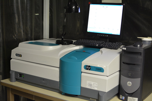
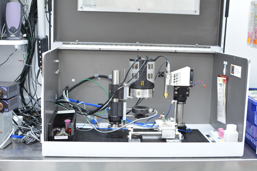
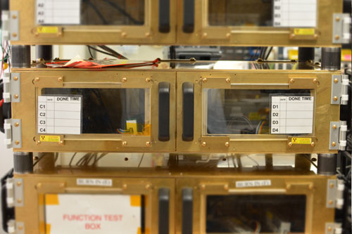
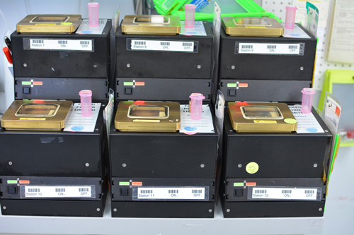
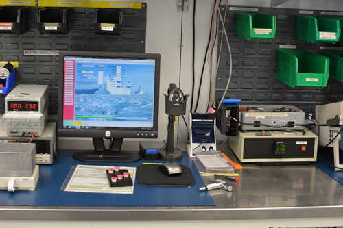
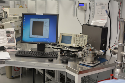
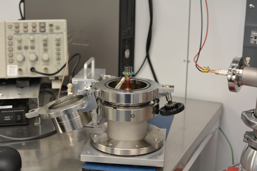
Our products are well characterized during development; once in production we continue to monitor the quality of the product with regular in-line testing. This allows us to control our processes as well as ensure the quality of products we deliver.
We characterize our products across all specification ranges including environment, inputs, vibration sensitivity, and radiation leakage. We measure the performance using equipment specifically designed in conjunction with local universities and our own application experts.
When a product transitions into production, product and processes are both monitored for consistency with regular in line testing. Test results are monitored by our process engineers using standard statistical process control methods.
We want you to be confident in our products for your specific needs that's why we offer specialized testing. Contact us about the testing needs of your product's.
-
Pressure Cycling
-
Leak Testing
-
Outgassing
-
Temperature Testing
-
Humidity Testing
-
Corrosion Testing
-
Forward Burst Testing
-
Reverse Burst Testing
-
Gas Permeability
-
X-Ray Transmission
-
Light Transmission
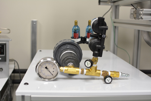
Windows are pressure cycled between 0 and 1.2 atm of differential pressure up to 10,000 cycles and then leak checked. Beryllium Windows go through a minimum of 25 cycles during in-line testing. This test mimics pressure cycles in and out of vacuum systems testing basic robustness.
AP Windows, DuraBeryllium Windows
X-ray Windows are leak tested on a helium leak tester to ensure leak integrity.
AP Windows, DuraBeryllium Windows
The ASTM (American Society for Testing and Materials) E595 test is intended as a screening test to determine if a material's outgassing characteristics are suitable for use in a vacuum environment.
AP Windows, DuraBeryllium Windows
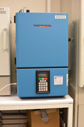
Polymer parts are cycled between -25°C and 70°C without differential pressure for a total of thirty cycles. Beryllium windows are taken up to 400°C during brazing process. Parts are checked for leak integrity before and after the testing. This test is preformed to mimic shipping extremes.
AP Windows, DuraBeryllium Windows, ProLINE WIndows
Parts are exposed to different humidity condition cycles, at elevated temperature for a minimum of 10 hours. This test is preformed to mimic shipping extremes and storage conditions.
AP Windows, DuraBeryllium Windows, ProLINE WIndows
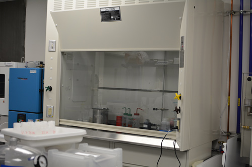
Parts are exposed to various corrosive environments and then checked for leak integrity. This test is preformed to find out what hazardous chemicals Beryllium windows can withstand.
AP Windows, DuraBeryllium Windows
Parts are exposed to differential pressure on the front-side, sample side, of the window until failure. This is the pressure differential the windows are designed for. This test is preformed to test ultimate pressure strength of the window.
DuraBeryllium Windows
Parts are exposed to differential pressure on the back-side, detector side, of the window until failure. This test is preformed to ensure window integrity in case of unintended pressure in the detector
AP Windows
Parts are pumped down on a mass spectrometer and exposed to specific gas environments for extended periods of time. Steady state diffusion of various gasses, such as nitrogen, oxygen, etc, are measured through the window with a Residual Gas Analyzer (RGA).
AP Windows, DuraBeryllium Windows
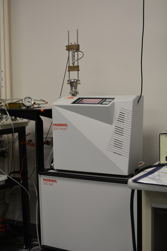
At Moxtek we do x-ray transmission measurement on a modified SEM. We have done x-ray transmission measurements at the Advance Light Source (X-ray Synchrotron Source); this gives the x-ray transmission, which is a primary characteristic of the x-ray windows.
AP Windows, DuraBeryllium Windows
A light spectrum is measured through window parts to characterize light tightness. X-ray detectors typically need a light-tight environment. All windows are visually inspected under a microscope during in-line testing to ensure no pin-hole defects.
AP Windows, DuraBeryllium Windows
-
Radiation Shielding
-
Spot Imaging
-
Production X-ray Final Test
-
Photon Flux
-
Thermal Shock Test 1
-
Thermal Shock Test 2
-
Thermal Shock Test 3
-
Adhesion Testing
-
Operational Temperature and Humidity
-
Development Stability Test
-
Conditioning Test
-
Development Multi-settings Test
-
Tube Impedence Test
-
Vibration Emission Frequencies
Testing stray radiation levels at fixed distances from the source while it is at maximum power (to simulate the highest radiation condition).
End Window Sources, Side Window Sources
The spot image of the source is captured by a CCD pinhole camera while source is powered at various current and voltage settings. The images are then analyzed for size, shape and movement.
End Window Sources, Side Window Sources
The source is powered to typical operating conditions, and the number of x-ray counts is recorded over a fixed time period. The test is repeated multiple times in order to calculate relative standard deviation (%RSD). Hundreds of settings are tested to ensure product is fully functional overall source settings.
End Window Sources, Side Window Sources
A bare tube is operated at a specific power level for a set amount of time. X-ray events are summed and divided by current (uA) to calculate flux in CPS/uA. Test is performed to ensure consistent flux from tube to tube.
End Window Sources, Side Window Sources
The bare tube is submerged in liquid nitrogen for 5 minutes the immediately transferred and submerged in boiling water for 5 minutes and tested for vacuum integrity. The test is then completed again, but in reverse order. Vacuum integrity is again tested.
End Window Sources, Side Window Sources
The bare tube is submerged in liquid nitrogen for 8 minutes. After 8 minutes, the filament current is turned on to 120% of maximum operating specification and tested for functionality.
End Window Sources, Side Window Sources
The bare tube is submerged in liquid nitrogen followed by boiling water four times, for 5 minutes each. After final cycle the part is subjected to physical shock and tested for functionality.
End Window Sources, Side Window Sources
End window sources have the anode deposited directly on the beryllium window. Target material coating is tested on a statistical sample using a stud pull-test to verify adequate adhesion of the anode to the window.
End Window Sources, Side Window Sources
Source is tested for full functionality while being operated at full power at the extreme temperature and humidity specification levels.
End Window Sources, Side Window Sources
In this test we measure flux stability directly from the source, high voltage stability from the bremsstrahlung edge, spot stability, power draw, and monitor all input and output lines over time.
End Window Sources, Side Window Sources
This test conditions the tube to ensure low-leakage current at over voltage.
End Window Sources, Side Window Sources
In this test, the source is run over 300 - 13,000 settings at different voltages and emission currents. At each setting the turn-on time, x-ray flux (measuring flux linearity), and stability of all inputs and outputs is measured.
End Window Sources, Side Window Sources
A set current is put through a filament to heat it up, the change in resistance is then measured to verify proper sealing of tube and good vacuum.
End Window Sources, Side Window Sources
The source is measured for mechanical vibration resonance frequencies using a piezo electric disc.
End Window Sources, Side Window Sources
-
Cooling Stablility
-
Cooling
-
Peak to Background
-
Spectral Purity
-
ICR/OCR Throughput
-
Outgassing
-
HASS
-
Resolution
-
Environmental Testing
-
Resolution Stability
-
Detector TEC Impedance
-
Wire Bond Strength
-
Microphonics
The entire assembly is held at an elevated temperature and power cycled for 12 hours. The cooling stability is measured over the same period.
Si-Pin Detector, Encapsulation
Measure module temperature drop over three minutes at max voltage.
Si-Pin Detector, Encapsulation
An Fe55 isotope is used at 20µsec peaking time and the number of counts in the Fe55 Kα peak (5.895keV) is divided by the average background at either 1keV or 2keV. This test is performed to ensure low peak to background, which allows for clean trace element detection.
Si-Pin Detector
This test is for testing self XRF noise generated by the components in the detector. A beam of x-rays scattered off a plastic target, which is devoid of XRF signals, impinges the window, collimater, and detector. Any XRF signal detected is self generated and recorded.
Si-Pin Detector
Number of x-ray events detected divided by the number of actual events, using DPP.
Si-Pin Detector
Outgassing of detector and components done by vendor to ensure proper vacuum integrity, which leads to proper cooling of detector.
Si-Pin Detector, Encapsulation
HASS testing (Highly Accelerated Stress Screening) is a screening method used to find defects in manufactured prodcuts. It is used to improve reliability in the field.
Si-Pin Detector
Resolution tests measure full width half max at Mn Ka, using DPP. Peaking time verses resolution is then measured at 50% dead time from 4us to 30us using Fe55 isotope.
Si-Pin Detector
The detectors performance is measured at temperature and humidity extremes.
Si-Pin Detector, Encapsulation
The parts resolution is measured repeatedly over an extended period of time.
Si-Pin Detector
Thermal electric cooler electrical impedance is measured.
Si-Pin Detector, Encapsulation
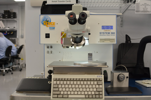
The parts ball bond shear strength and pull strength is measured using Royce instruments universal bond tester.
Measure detector resolution shift in the presence of 100 dB of white noise. This ensures our detectors work in all types of industrial, noisy environments.
Si-Pin Detector

